- Home
- Industries
- Refining
- Hydrocracking
Hydrocracking
Increasing the safety and efficiency of the hydrocracking process for the fixed bed and ebullated bed
 MOGAS valves are designed to isolate the most severe, nastiest media in any industry.
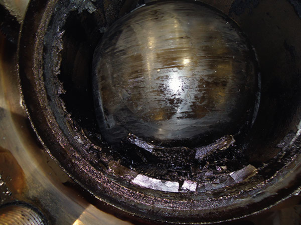
When processing residual heavy oils, mechanical equipment is punished by high pressure, high temperatures and corrosive/erosive media, such as salt, particulates, metals, sulfur and naphthenic acids. The heavier the feedstock, the higher temperatures and pressure needed to break apart hydrocarbon molecules, and the more difficult it is to enclose and hold pressure from leaking out. In main process lines where temperatures range from 450 to 1500°F (230 to 815°C), fluid streams become heavier, more viscous and tougher to handle. Waxes start to build up and asphaltenes solidify. Also, when temperatures increase, coke is formed and builds up in pipe elbows and mechanical equipment — such as pumps and valves — plugging flow paths and eroding metal surfaces. Complications from this type of crude push refinery infrastructures to their limits as plants are always looking to make units more profitable, more reliable, safer and in compliance with environmental requirements.
MOGAS valves are engineered to withstand the most severe conditions. Special trim and purging configurations for high pressure and temperature coking services and technologically advanced coatings make our isolating design the most-trusted in any industry. In fact, MOGAS is the only manufacturer with valves installed in EVERY ebullated bed unit worldwide—totaling well over 10,000 valves. Our experience in the industry remains unmatched.
Typical Operating Conditions:
- High Temperatures: 300 – 1000°F
- High Pressure: 1000 – 3500 psi
- High Pressure, High Temperature Hydrogen
- High Pressure, High Temperature Catalyst Handling
- Coking Service
- Viscous Sludge
- Asphaltene Formation
- Ammonium Bisulfide Corrosion
- Hydrogen Sulfide Corrosion
- Polythionic Acid Corrosion
-
MOGAS is the only manufacturer with valves installed in EVERY ebullated bed unit worldwide — totaling well over 10,000 valves.
With only a limited number of ebullated-bed hydrocracking units in existence globally, finding a valve manufacturer that understands the process could be more arduous than the process itself.
For almost 30 years, MOGAS has worked in concert with the only two licensors of this technology to develop coatings and valve designs that can withstand this demanding process with 100 percent reliability for a unit’s entire 4 to 5 year run-time. Our experience, performance record, and dedication to continuous improvement have made MOGAS the preferred vendor for this unique process technology.
Ebullated Bed Process Flow Diagram
- Chopper
- Hydrogen Heater Inlet Emergency Block
- Feed Heater Outlet Emergency Block
- Hydrogen Heater Outlet Emergency Block
- Reactor Catalyst Addition
- Reactor Catalyst Withdrawal
- Hot High Pressure Separator Automated LCV Isolation
- Hot High Pressure Separator Manual LCV Isolation
- Hot High Pressure Automated Overhead Vapor Isolation
- Hot High Pressure Manual Overhead Vapor Isolation
- Cold High Pressure Separator Automated LCV Isolation
- Cold High Pressure Separator Manual LCV Isolation
- Hot Intermediate Pressure Separator Automated LCV Isolation
- Hot Intermediate Pressure Separator Manual LCV Isolation
- Unit Depressurization
- Rich Amine Manual Isolation
- Pre-heater Pump Drain
- Pre-heater Pump Isolation
-
As the more common of the two hydrocracking processes, fixed-bed technology is in place in roughly 700 units globally.
MOGAS’ experience with the process is almost as broad as the technology itself. In fact, MOGAS works with licensors of fixed-bed technology to improve the performance of valves in isolation applications to make the hydrocracking process safer and more efficient.
Fixed Bed Process Flow Diagram
- Chopper
- Recycle Gas Compressor Surge
- Rich Amine Isolation
- Sour Water Isolation
- Cold High Pressure Separator Automated LCV Isolation
- Cold High Pressure Separator Manual LCV Separation
- Hot High Pressure Separator Automated LCV Isolation
- Hot High Pressure Separator Manual LCV Separation
- Frac Bottoms Emergency Block
- Frac Bottoms Pump Isolation
- Unit Depressurization